Direct Online Starter Animation Diagrams Electrical Online 4u
The three-phase system provides a more efficient and balanced power distribution, resulting in smoother motor operation. One of the crucial steps in wiring a three-phase motor is determining the motor's voltage and current requirements. This information is typically stated on the motor's nameplate, and it's important to ensure the motor.

Single Phase Motor Wiring Diagram Star Delta
What is a 3 Phase Motor? A three-phase motor is a type of electric motor that operates on three alternating current (AC) power lines. It is commonly used in industrial and commercial applications for its efficiency, reliability, and power output.

3 Phase 240V Motor Wiring Diagram Collection
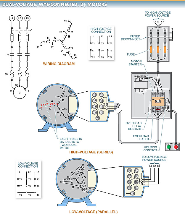
It provides internal connection diagrams for three-phase windings. It can be used with either concentric or lap windings. It also covers all possible parallels; wye and delta, 2 - 48 poles; part windings; two-speed windings; wye-delta and consequent-pole connections, 2 - 48 poles.
Wiring Three Phase Motor
The ability to understand and interpret a three phase motor wiring diagram is essential for the successful operation of electric motors. From industrial settings to residential homes, three phase motor wiring diagrams are an important tool for powering electric motors. Knowing how to interpret and apply these diagrams can help electricians troubleshoot motor problems and ensure proper.

Fine Beautiful 3 Phase Motor Connection Light Detector Circuit Using Ldr
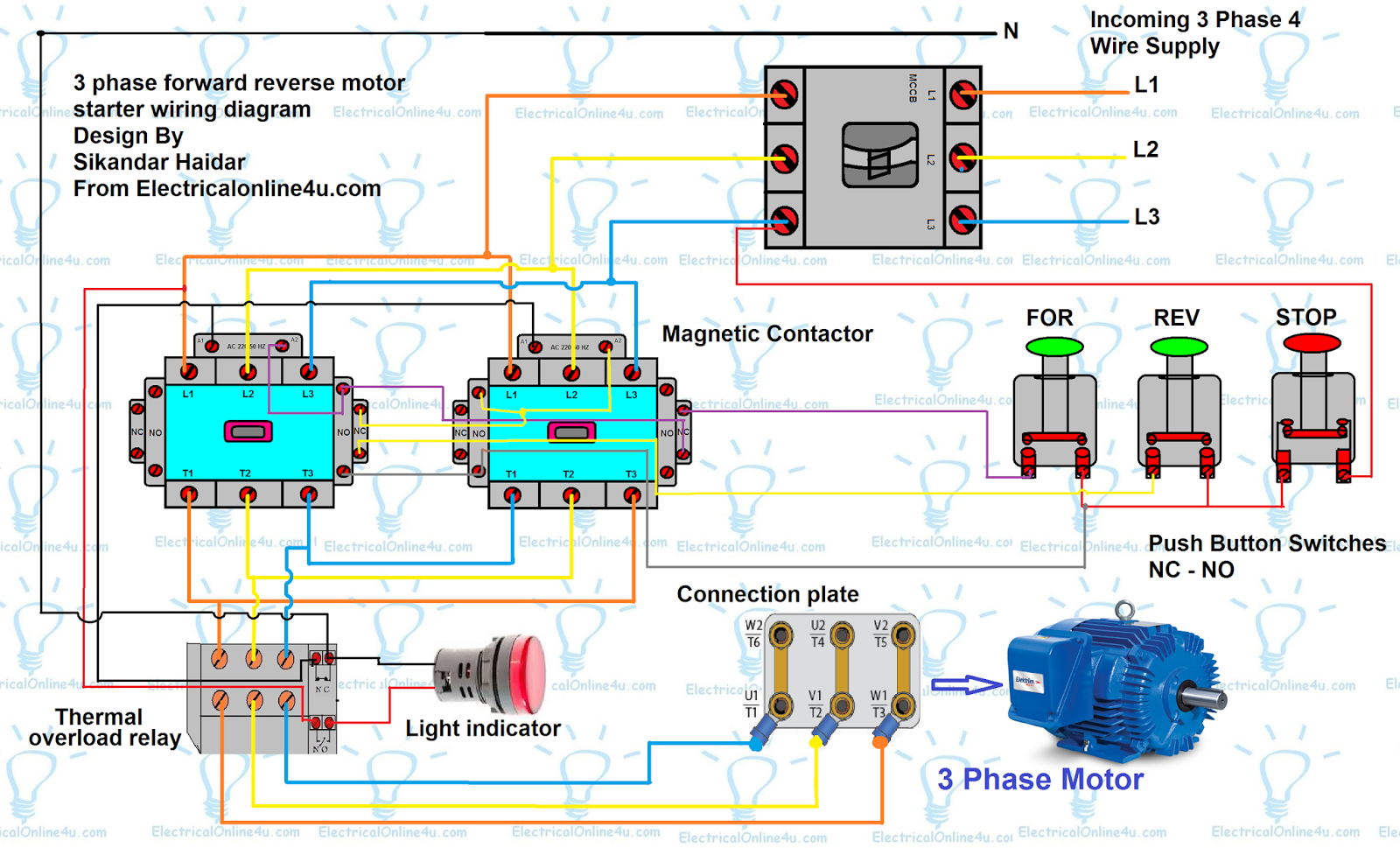
Wiring diagrams, sometimes called "main" or "construc-tion" diagrams, show the actual connection points for the wires to the components and terminals of the controller. They show the relative location of the components. They can be used as a guide when wiring the controller. Figure 1 is a typical wiring diagram for a three-phase mag-

480V 3 Phase 6 Lead Motor Wiring Diagram PUVQWR
Three-phase motors use coils of wire to create magnetic fields and produce rotation. Standard 3-phase motors use six individual coils, two for each phase. The internal construction and connection of these coils inside of the motor is predetermined when the motor is manufactured. There are two classes of 3-phase motors: Wye and Delta.
AC Motor Types Working Principle Single & Three Phase AC Motors
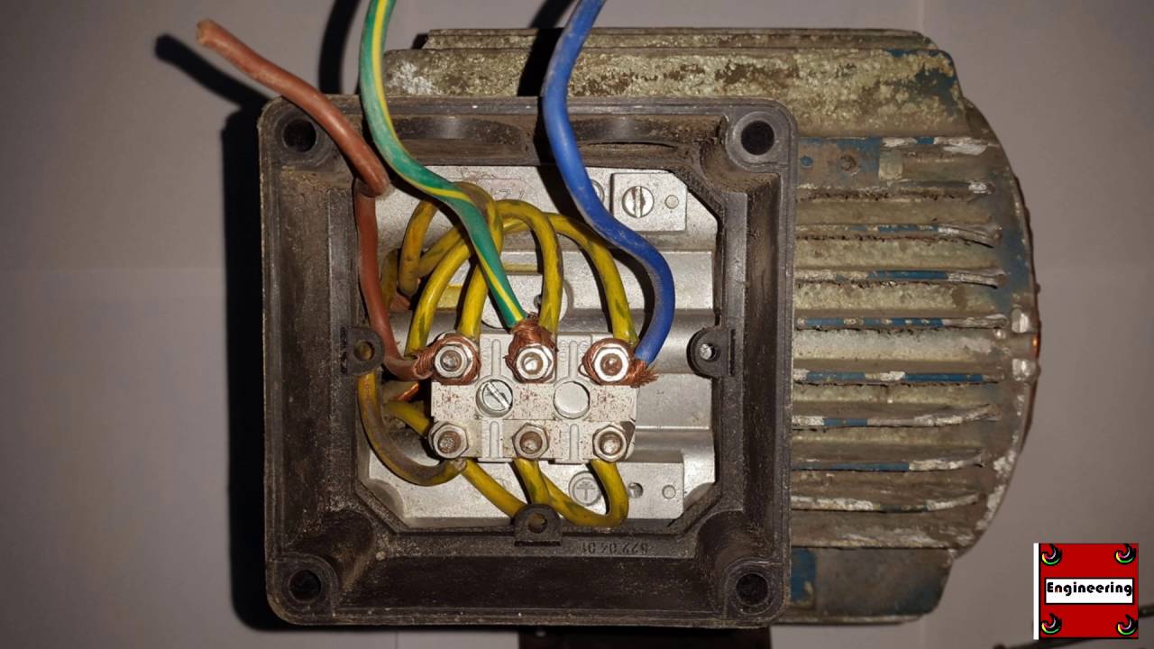
The most common type of three-phase motor is that which has nine labeled (and often colored) wires coming out of the box on the side. There are many motors with more or fewer wires, but nine is the most common. These nine-wire motors may be internally connected with either a Wye (star) or a Delta configuration, established by the manufacturer.
Forward Reverse Motor Control Diagram For 3 Phase Motor
Three Phase - 3 Lead Motor. Find 3 Phase Electric Motor Wiring Diagrams for 12-Lead Motors, 9-Lead Motors, 6-Lead Motors, and 3-Lead Motors here.
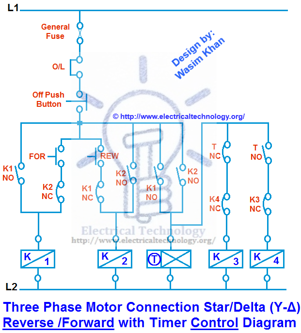
Three Phase Motor Connection Star/Delta (YΔ) Reverse / Forward with Timer Power & Control
Three-phase synchronous motors can be purchased with a variety of wiring styles. The most common is nine-wire, but there are also many examples of motors with three, six, or even twelve wires. Of all types, the twelve-wire motor provides the most options for connecting based on voltage and system configuration (wye or delta).

Start Stop 3 Phase Motor Starter Wiring Electrical Engineering Updates
Wiring Procedure Step 1: Identify the Wires Identify and sort the 9 or 10 wires. 3 are power wires, and 6 or 7 come from the motor. The wires are color-coded, but some also have numbers written on them. Refer to the wiring diagram on the motor's label. Video | Wayne's Garage Step 2: Choose a Configuration Which configuration should you make?
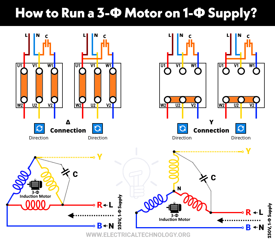
Hubschrauber Herstellung Hostess difference between single phase and three phase power supply
In this lesson we'll learn to interpret motor connection diagrams for 3 lead Y, 3 lead delta, 6 lead, 9 lead Y, 9 lead delta, and 12 lead 3 phase AC motors..
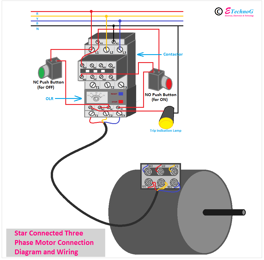
Three Phase Motor Connection Diagram and Wiring Procedure ETechnoG
Three-phase AC motors can be divided into three general types: squirrel-cage, wound-rotor and synchronous. Only the squirrel-cage rotor motors and the wound-rotor motors are induction motors. The rotor circuit in an induction motor does not have an external power supply.

Wiring A 3 Phase Motor With A High Leg
Each of the three phases has 2 coils on opposing sides of the motor. This creates a well-balanced push and pull applied to both sides of the motor equally at any given time. A normal 3-ph synchronous motor has 6 separate bundled coils of wire around the outside of the housing. In a 3-phase motor, the direction of rotation is quite predictable.

motor connection diagram three phase Wiring Diagram and Schematics
Steps. Download Article. 1. Check power source. Ensure that any electrical power fed into power cord, is shut off prior to working on motor. 2. Prepare power cord. Using a pair of diagonal cutters, cut and remove 3 in of rubber insulation around outside of power cord. Revealing four wires inside cord.
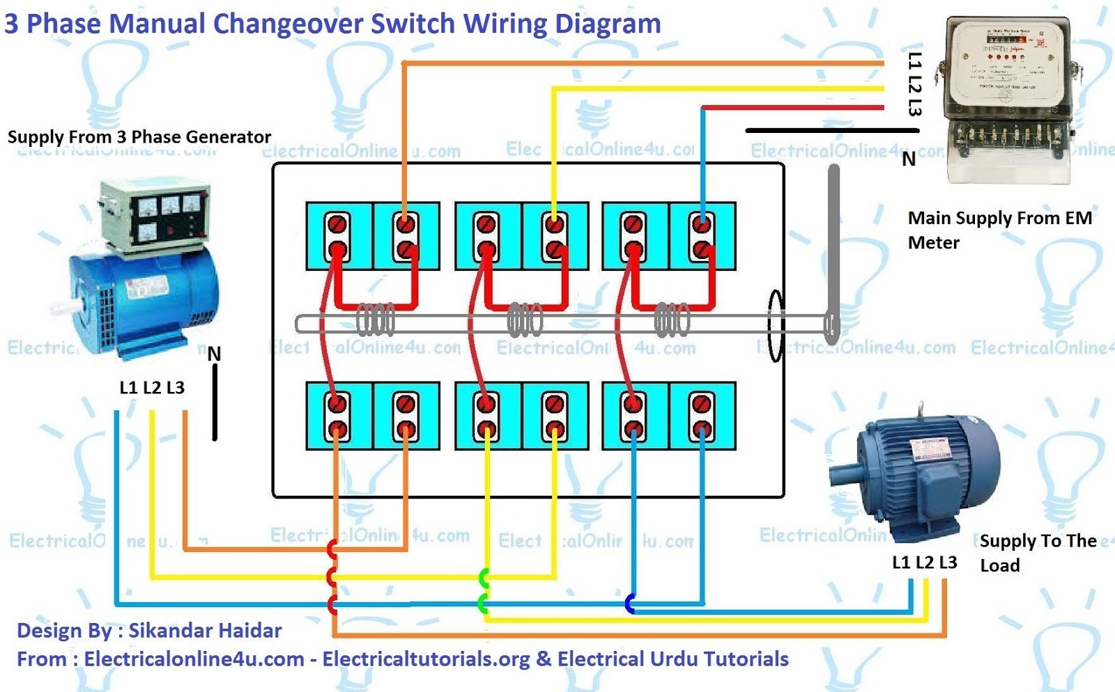
Electrical 3 Phase Switch Wiring Diagram
Main and auxiliary circuit diagrams of switching three-phase motors via contactor and directly In general, the graphic symbols in circuit diagrams are represented in a de-energized and mechanical non-operated state. Deviations from this rule mu be clearly indicated in the circuit diagrams.
3 Phase Motor Circuit Diagram
23 1 minute read Three Phase Motor Power & Control Wiring Diagrams Three Phase Motor Connection Schematic, Power and Control Wiring Installation Diagrams. Star-Delta (Y-Δ) 3-phase Motor Starting Method by Automatic star-delta starter with Timer. Three Phase Motor Connection STAR/DELTA Without Timer - Power & Control Diagrams